
PV Condition Assessments: NYC Commercial Solar
Comprehensive, independent written reports on the technical condition of your commercial solar system. Built for asset owners who need objective data, not installer talking points.
A Technical Report Built for the Owner
A PV Condition Assessment (PVCA) is a structured, documentation-based review of a solar system's technical condition. It is not a sales call. It is not a routine PM visit. It is a formal engineering assessment that produces a written deliverable.
The assessment covers every major system component: electrical, mechanical, thermal, monitoring, and production performance. The output is a written report you can use for insurance, financing, management decisions, or vendor negotiations.
NABCEP is the gold standard for solar industry certification. The PVSI credential is specifically for inspection professionals, not installers.

Infrared Training Center certification behind the thermal imaging in every assessment.
What the Written Report Covers
Delivered within 5 business days of the site visit. All findings documented with photographic evidence.
01: Electrical Integrity
- DC termination torque and condition
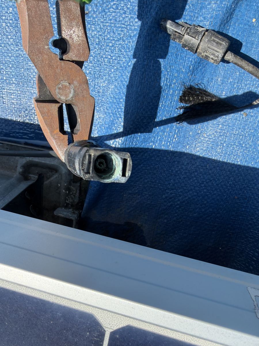
- MC4 connector condition and weatherproofing
- Grounding conductor continuity and connections
- Conduit and wiring management
- Labeling compliance and circuit identification
- Combiner box and disconnect condition
02: Thermal Imaging
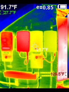
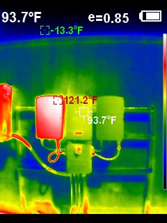
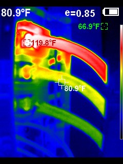
- Full array infrared scan during active production
- Hot cell identification (cracked cells, bypass diode failures)
- DC combiner and terminal block thermal review
- Inverter heat management assessment
- Delta-T classification per IEC 62446-3 reference ranges
03: Structural & Roof Interface
- Racking hardware and fastener condition
- Roof penetration and flashing condition
- Array drainage: standing water risk points
- Corrosion and weathering assessment
- Panel condition: visible physical damage, soiling
04: Performance & Monitoring
- Production vs. modeled output comparison
- String and optimizer performance analysis
- Monitoring platform configuration review
- Alert history and communication gap analysis
- Inverter event log review
05: Inverter & Component Lifecycle
- Inverter model and production year
- Estimated remaining design life
- Warranty status: original, extended, expired
- Firmware version and known issue review
- Capacitor replacement considerations (electrolytic inverters)
06: Recommendations
- Findings prioritized by severity (immediate / near-term / long-term)
- Specific repair and maintenance recommendations
- Array cleaning interval recommendations based on observed soiling
- Cost-impact analysis for major findings
- Suggested follow-up actions
What an Infrared Scan Actually Shows
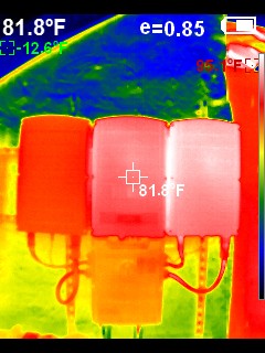
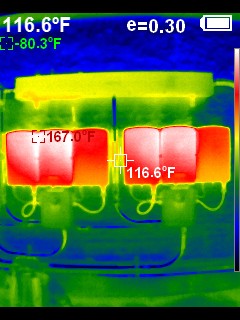
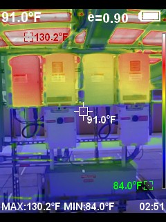
Example captures from field assessments: infrared scans of combiner boxes, disconnects and inverter enclosures, each reading spot and reference temperatures against the surrounding baseline. This is the raw data behind the delta-T classification in the written report, not a stock photo of a thermal camera.
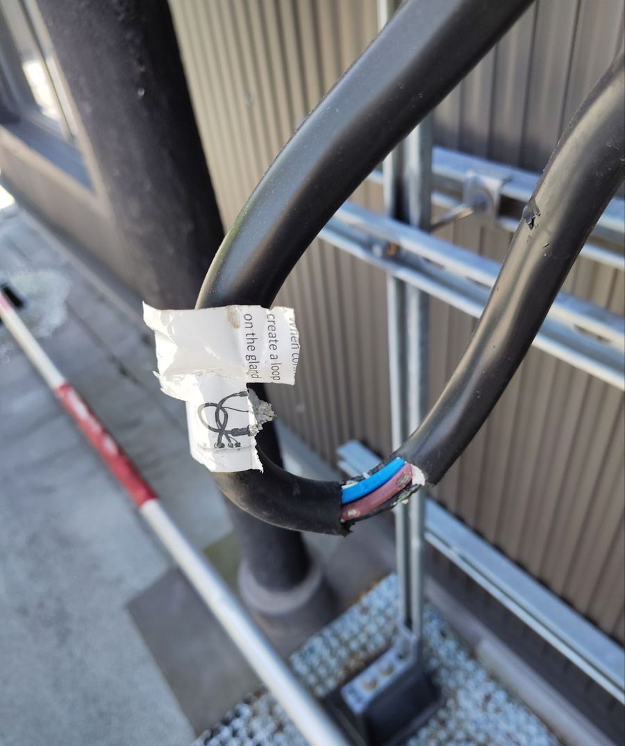
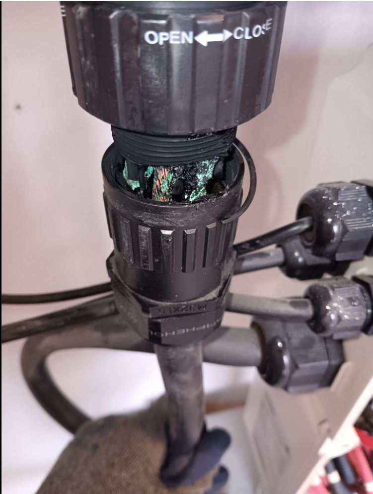
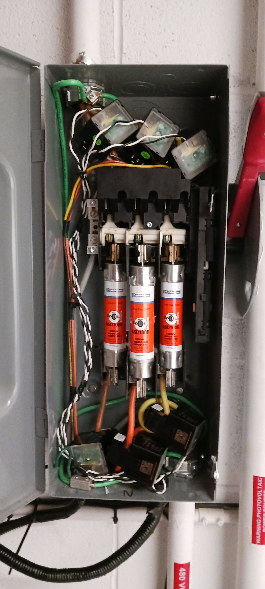
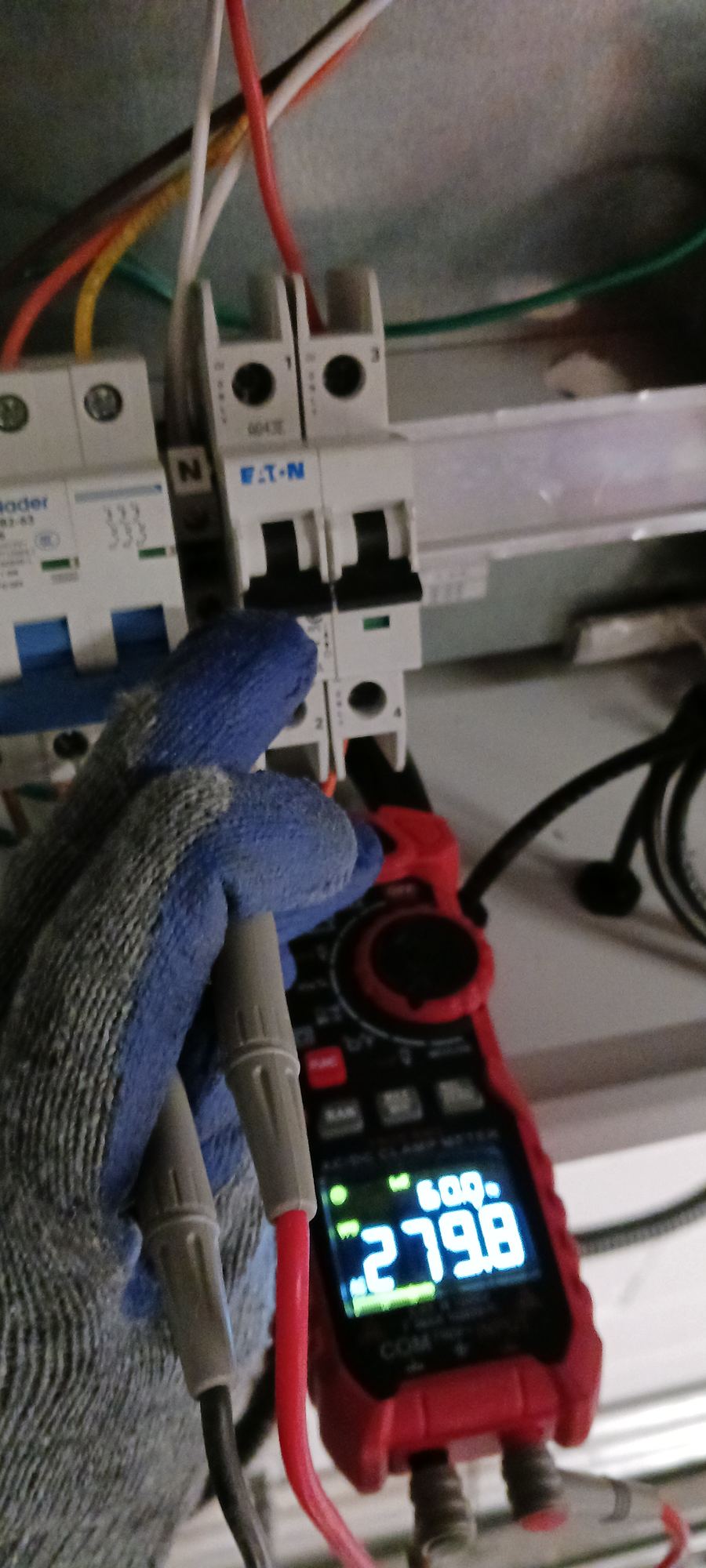
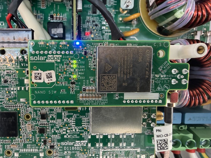
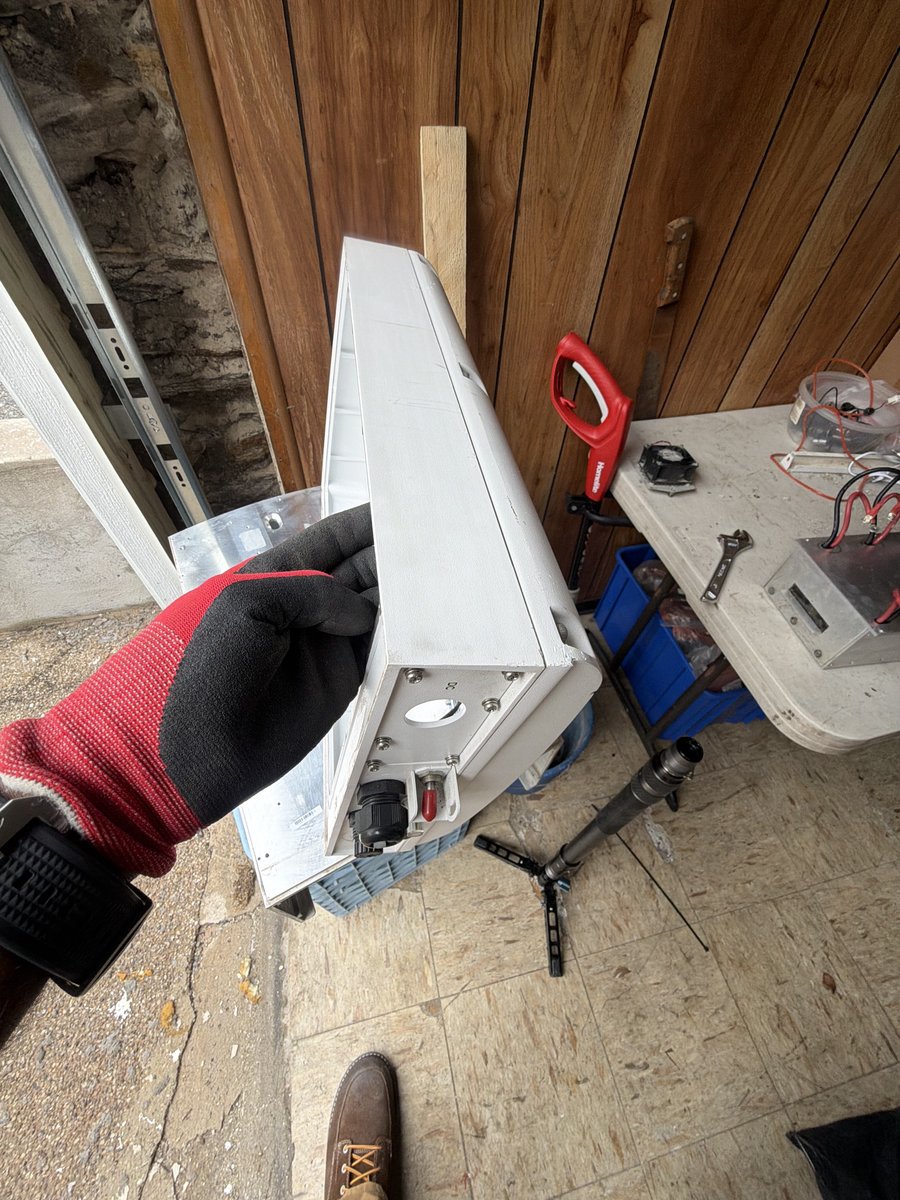
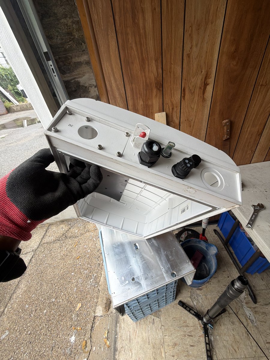
What Section 01 Findings Actually Look Like
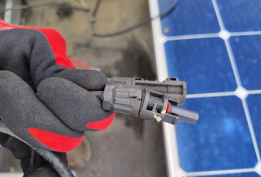
Real findings from field assessments: cracked connectors, corroded terminations, damaged conduit glands. This is the visible evidence behind an "immediate priority" line item in a written report.
When Building Owners Commission an Assessment
Your monitoring shows lower output than expected and your O&M provider's explanation doesn't satisfy. An independent assessment finds the actual cause.
You're buying a building with an existing solar lease or ownership arrangement. Know what you're inheriting before closing.
Lender or insurer requires a technical review. We provide written documentation acceptable for commercial financing.
Evaluate your current O&M provider's performance with objective data before renewing or switching.
5 years, 10 years, or approaching inverter warranty expiration. Structured review identifies risks before they become failures.
Storm damage, rodent damage, or other casualty event. Independent assessment documentation supports the claim.
Request a PV Condition Assessment
Independent written reports for commercial solar systems. NYC, North Jersey, Connecticut, and Antigua.